Simply Upgrade Your Existing Chassis Dyno!
Battery Fast Charging Station HPDC 1000/400
The DC charging station serves as a high speed charging station for electric vehicles with a DC voltage connection directly at a already existing stationary road drive simulation test bench.
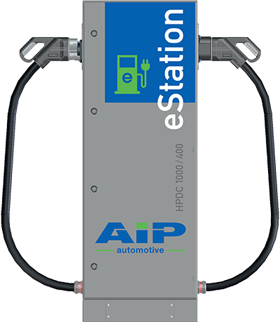 It consists of a charging station, which is placed near the vehicle in the test cell or soak room and a power unit, which is located e.g. near the power control cabinet of the test bench. The power electronics for generating the regulated DC charging voltage is preferably connected to the existing DC link of the motor converter (test bench power supply cabinet) of the existing vehicle test bench.
This adaption is manufacturer-independent, as long as certain technical marginal parameters are kept. Alternatively (optional), a separate DC link Feed unit may be used, which e.g. becomes necessary for EMC chassis dynos from AIP.
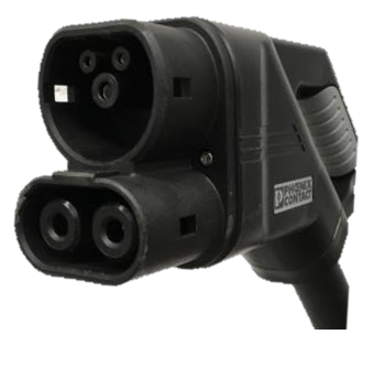
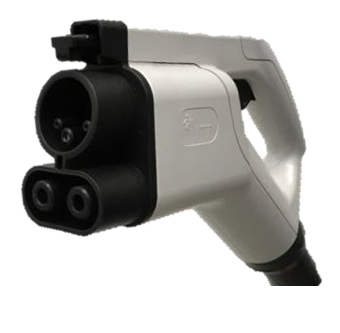
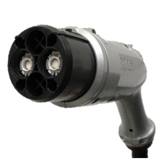
The HPDC charging station can be equipped with the 4 international charging standards CCS1, CCS2, CHAdeMO and GB/T. It is possible, to use the two combined charging systems (CCS1+2) as uncooled charging lines or as liquid cooled charging lines for the High Power Charging (HPC) with current to realize up to 400 kW charging power.
CCS2
CCS1
CHAdeMO
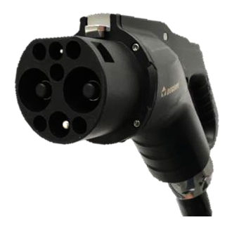
GB/T
'Master-System'
'Slave-System'
The required communication with the test vehicle during DC charging is taken over by a charging controller, which controls the various charging standards. The test vehicle acts as a master system and the charging station sets the required charging parameters as a slave system.
In addition, the complete charging infrastructure can be integrated into existing safety systems such as emergency stop, fire alarm, etc.
Advantages of the HPDC 1000 charging technology
- Easy integration into existing test bench safety chains
- No additional energy supply necessary
- Compact, flexible system structure
- Energy recovery capability (controlled energy return into the network, if supported by the test vehicle). This enables, for example:
– the preparation of the transport for relocation by means of a transport vehicle
– automated charging / discharging cycles with plugged-in charging plugs (optional)
- Optimized cable lengths, thereby
– reduced risk of accidents due to tripping hazards
– improved handling in tight spaces and
– Improved handling with different positions of the charging sockets on the test vehicles
– reduced acquisition and maintenance costs
- Direct coupling with the electrical feed of the test stand
- Can be implemented modularly from 100 kW… 400 kW
- High-performance charging up to 400 kW
- Implementation of several charging points with just one power electronics
- Optional extended operating temperature range for use in air conditioning cells / wind tunnels
- Future-proof retrofittable, e.g. for:
– power expansions
– new charging connector standards, e.g. ChaoJi
- Integration into the existing software environment / automation of the test bench
- Software for setting performance parameters
- Implementation of all current charging standards in just one product
- Vehicle communication data logging
- Loading of defined SOCs
- Supply of up to 4 charging points in 100 kW steps
- High quality charging plug (from the market leader), can be repaired by the customer if necessary.
Application field
- The charging system can be used, for example, as an upgrade to the following test bench systems:
- Chassis dynamometers (Mileage accumulation)
- Powertrain Dynamometers
- EMC Chassis dynamometers (optionally)
- Flat road dynamometers
- Charge / discharge cycles of complete vehicles in climatic chambers
Example of HPDC 1000/400 Charge
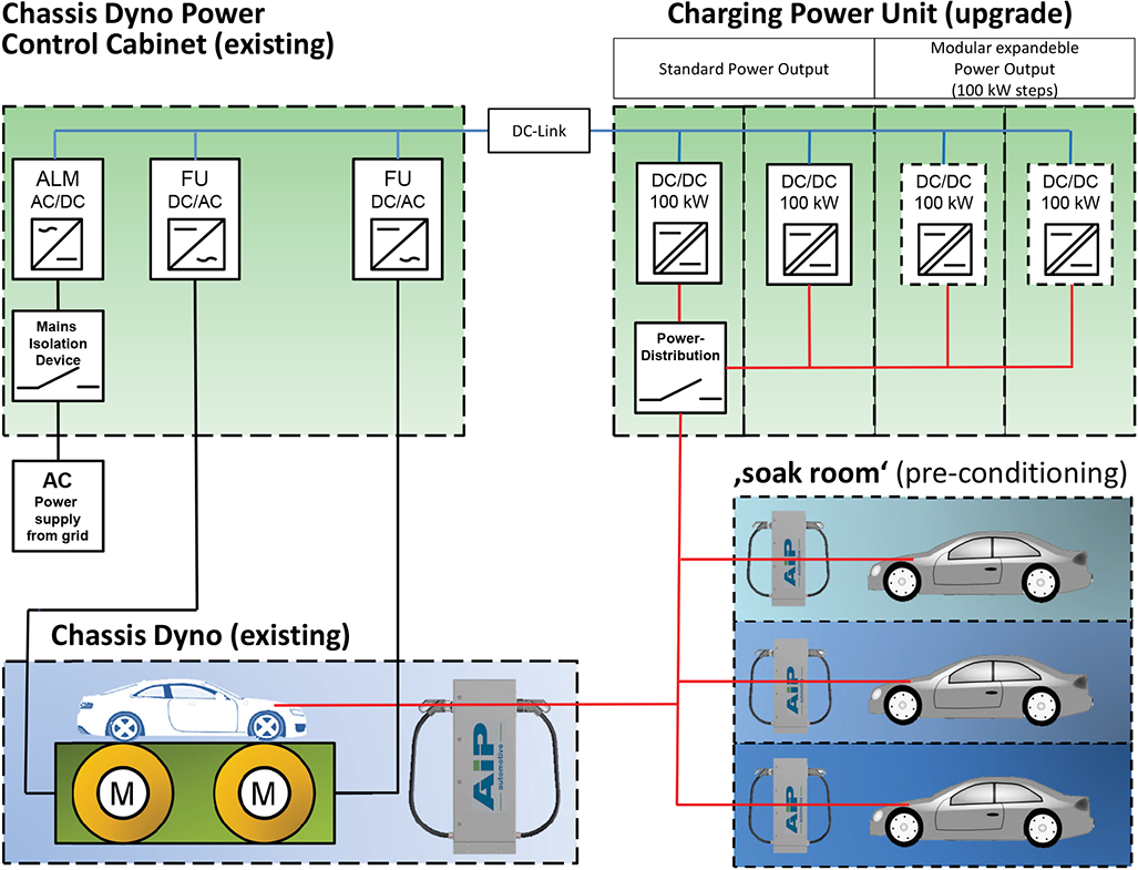
Example HPDC 1000/400:
1000 V voltage range, max. 400 kW charging power, divided e.g. into 4 vehicles of 100 kW each (1 x vehicle on a roller test bench, 3 x vehicle in a conditioning room).
Technical Data
| Power range |
100 ... 400 |
kW |
| max. charging power per charging point |
400 |
kW |
| Output voltage range |
50 … 1000 |
V |
| Charging current max. |
500 |
A |
| Efficiency |
94 |
% |
| Functionality |
| Plug types |
CCS1, CCS2, CHAdeMO, GB/T |
|
| Number of charging options |
4 |
|
| Temperature range |
-35 … +50 |
°C |
| Protection class |
IP 54 |
|
| Operation |
Control via test bench computer |
|
| Optional |
7" Touch-Display |
|
| Dimensions |
| Dimensions charging station (W x D x H) |
500 x 500 x 1500 |
mm |
| Dimensions charging unit (W x D x H) |
on request |
mm |
| Weight of charging station |
ca. 240 |
kg |
| Material |
Powder-coated sheet steel |
|
| Housing of power electronics (W x D x H) |
2200 x 600 x 2400 |
mm |