E-Pulser
Precise examination of noise sources, e.g. vehicle interieur ('squezze and raddle'), enduance tests, component testsm fatique tests, etc., under dynamic loads. The AIP designed and fabricated E-Pulser, electrodynamic drive concept offers various advantages, compared to common servo-hydraulic systems.
Application
The reproducible excitation of the test vehicle is achieved by simulated driving profiles (driving files) or by artificially generated vibration profiles, e.g. sine, square, triangle, noise or other road profiles.
Depending on the requirements of the test tasks or test specimens (complete vehicles or components, e.g. axle, shock absorber,etc.), the E-Pulser simulation test stands can be one-poster system up to multi-post systems.
- One poster system (shock absorber, component test, etc.)
- Multi-poster system (road simulator, exhaust line test, etc.)
- Multi-poster system (fender test, shaker, movements with 6 degrees of motion)
Quality Benefits
Critical driving ranges can be driven reproducible, repeatedly, modified and or reinforced without limits using dynamic road simulators. An exact analysis can be presented in detail concerning possible sources of disturbances and influencing variables.
Cost Advantages
With electric pulsers/versus hydraulic pulsers), installation and maintenance is simpler, quiker, less expensive, clean, no leaks...
E-Pulser Road simulators are usually used in conjunction with climate chambers and solar systems to achieve a substantial reduction in costs and time, when compared to conventional testing involving real road driving under variable, reproducible, climatic conditions.
The excitation of the vehicle is done by recreating drive profiles (drive files) or by artificially generated oscillation profiles, e.g. sine, rectangle, triangle, noise or other road profiles.
Test Environment
| Temperature of test chamber |
-25 ... +60 |
°C |
Temperature of E-Pulser environment (basement)
(see option extended temperature) |
+10 ... +35 |
°C |
The E-Pulser is suitable for light duty test vehicles with the following data (Example)
| Vehicle mass max.* |
3,500 |
kg |
| Wheel load max:* |
1,000 |
kg |
| Axle load Front & Rear max. |
2,000 |
kg |
| Unsprung mass per wheel max: |
60 ... 150 |
kg |
| Wheelbase |
2,400 ... 4,000 |
mm |
| Track width |
1,450 ... 1,900 |
mm |
| Tire width max. |
350 |
mm |
Linear drive – electrodynamic
The test bench (4 pulser) is equipped with 4 electrodynamic linear drives:
Technical Features
- Linear guide
- Integrated measuring system with end position monitoring
- Pneumatic vehicle weight relief – zero position
- No sinking in the event of a fault
- Water cooling system with heat exchanger including piping
- Low position/zero level of pulser to be defined
Wheel Guidance
The wheel guidance is equipped with a circumferential, angled tire stop with rounded corners
On request: customized design possible, according to customer requirements
Test Bench Data (Example)
Other customized configurations on request.
| Wheel load static max. |
3,500 |
kg |
| Amplitude dynamic max. |
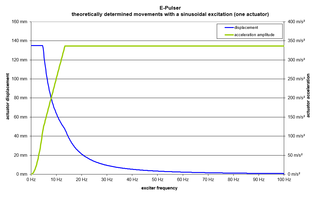
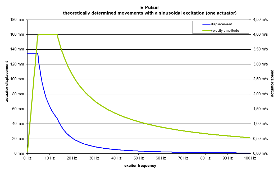
± 120, see Option ± 150 |
mm |
| Force (peak) |
40 |
kN |
| Frequency range |
0.2 - 100 |
Hz |
| Speed max. |
± 4.0 |
m/s |
| Acceleration max. (without test specimen) |
± 200 (20 g at 40 Hz |
m/s² |
| Accuracy displacement |
± 0.1 |
mm |
| Sampling rate displacement measurement min. |
2 |
kHz |
| Total power – simultaneity factor (4 actuators) |
0.3 |
|

| Distance inner-inner wheel contact area |
1,100 |
mm |
| Distance outer-outer wheel contact area |
2,200 |
mm |
| Track width min. |
1,450 |
mm |
| Track width max. |
1,900 |
mm |
| Tire width min. |
350 |
mm |

| Setting |
Rear axle adjustable, Front axle fix |
|
| Wheelbase min. |
2,400 |
mm |
| Wheelbase max. |
4,000 |
mm |
| Setting accuracy |
± 2 |
mm |
Vehicle database
Storage of vehicle data incl. automatic adjustment of wheelbase.
Optional Accessories/Features
- Extended amplitude: ± 150 mm
- Amplitude dynamic max.: ± 150 mm
- Vehicle position monitoring
Vehicle position monitoring is performed with electro mechanical 4 position switches, which are supplied ea. with a vertical stand.
Wheelbase Displacement
The clamping of the shifting units is performed with spring clamping cylinders (currentless clamped version).
The locking of the positioning device is functional even with maximum loads.
Positioning units consisting of:
- Electromechanical spindle system
- Spring clamping cylinder
- Incremental encoder for determining the position
- Absolute limit switches
- Control integrated in SPS
Pit Decking of the movable E-Pulser units
AIP is providing a decking plate including pneumatic lift system for each of the movable posters (total 2). The decking plate is lifted when wheelbase adjustment is activated. Wheelbase displacement is performed without vehicle. The sub system component thermal sealing interface between the insulation of the chamber and the E-Pulser is provided by the chamber supplier.
Optional: Center Pit – Sensor Plugin Panel
The center pit is usually provided by the climatic chamber supplier. A pocket should be formed in the middle of the pit wall aligned with the control room to accommodate the measuring technology connections.
The AIP scope of supply is providing the (standard) sensor plug-in panel in center pit with the integrated sockets for
- 4 analogue inputs ± 10 V; acceleration sensors provided by customer
- 4 temperature sensors PT 100, sensor provided by customer
Panel dimensions: (W x H x D) 600 x 700 x 150 mm
Standard Cabling (material from sensor panel to AIP control cabinet is included. The installation on side, cable trenches, etc. are optional, has to be arranged by the customer, based on the on site conditions.